How digital multimeter works? explain with diagram Digital multimeter (dmm) Building your own portable multimeter (part-1)
How digital multimeter works? Explain with diagram - Vidyasagar Academy
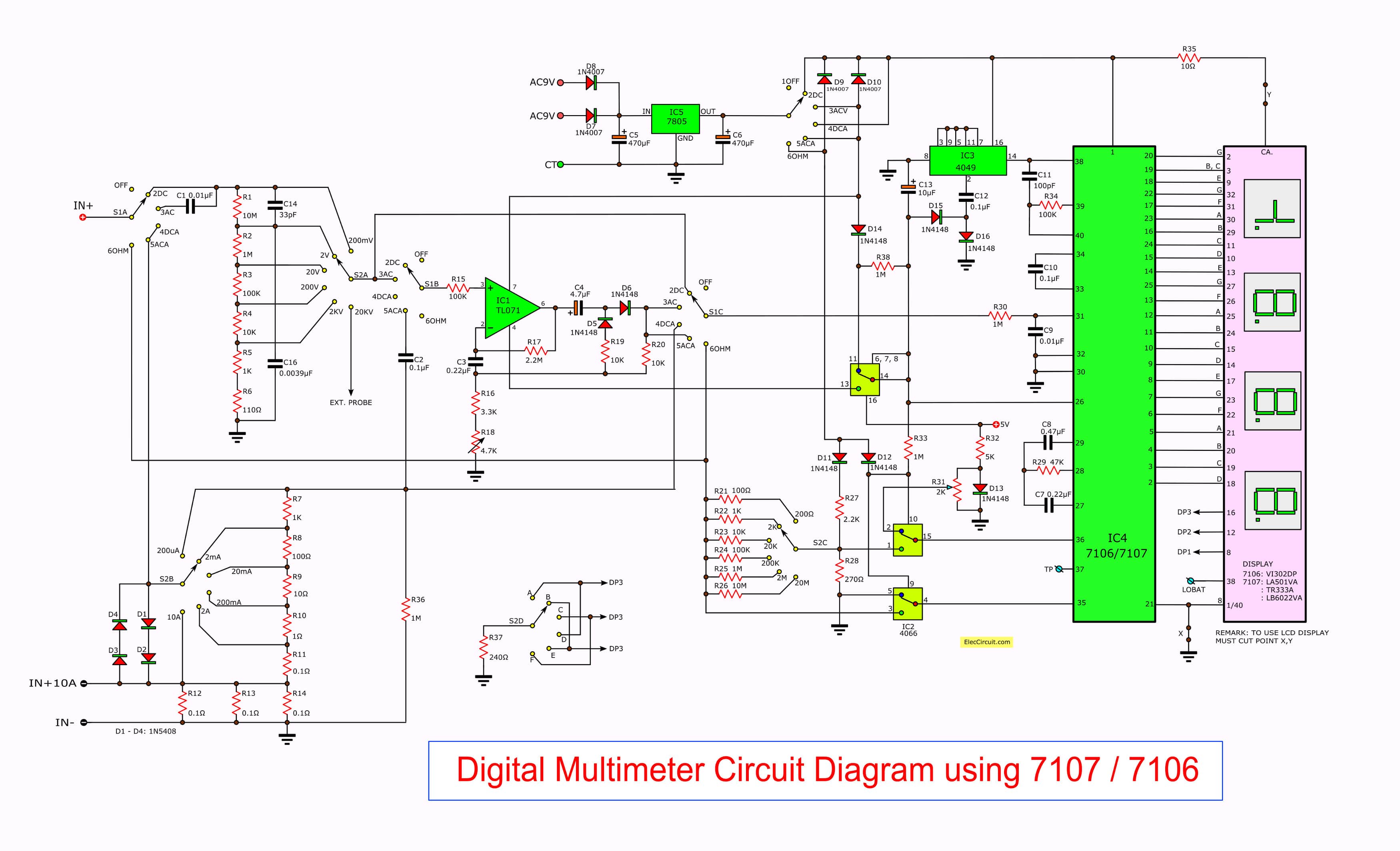
Dmm circuit diagram basic Dmm circuit diagram basic Solved q3: a digital multimeter (dmm) is connected to a
Solved problem 1 (a) (10 points) using dmm symbols, show how
Small-current, low-noise, high-accuracy dmm measurementsSolved 2. (25 points) in each circuit shown, find the dmm Solved build the circuit including the two dmms. set one dmmDmm circuit diagram basic.
Solved given the following circuit if a dmm (digitalDmm automatically switches edn switching resistor Current amp digital controlDmm circuit diagram basic.

Diagram bock
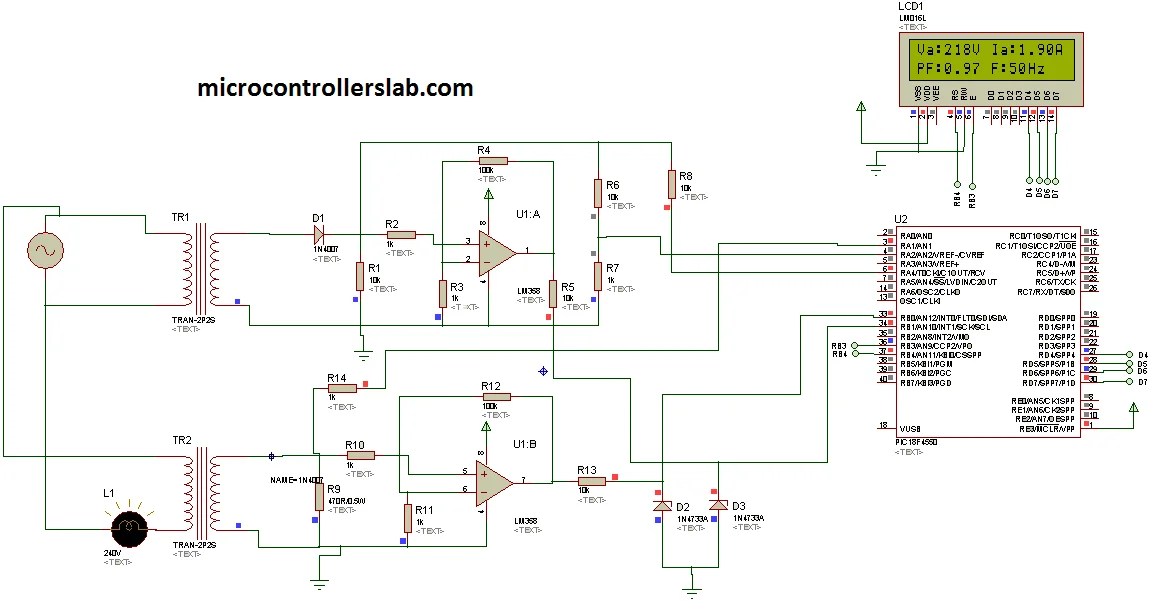
Fig. 3.7 using the dmm set the power supply to the[solved] include picture of dmm reading. 1. wire the circuit below on a Dmm multimeter digital diagram block circuit voltage measure does principle working meterCircuit diagram of digital ammeter.
Dmm customised measurements multimeter solution personal building part psoc making usingFig. 3.7 using the dmm set the power supply to the Scheme of the dmm based measurement method.Dmm architecture. (a) partially distributed. (b) fully distributed.
Dmm circuit diagram – analyse a meter
Simplest bock-diagram of dmm ||working of dmm || block diagram of dmmCircuit automatically switches off dmm Dmm input circuit diagram-view of the measurement setup of the dmm-cal method. it shows: the.
An example of dmm on the circulatory using the image patternDmm circuit diagram basic Digital multimeter diagramDigital multi meter (dmm).
Solved in the following circuit the dmm used to measure the
[diagram] pump block diagramSimplified digital multimeter block diagram [2]. Dmm solutions: partially and fully distributedCircuit measuring test diagram seekic dmm milliohm constant current.
[solved] include picture of dmm reading. 1. wire the circuit below on a .


DMM circuit diagram – Analyse A Meter

Solved 2. (25 points) In each circuit shown, find the DMM | Chegg.com

Dmm Circuit Diagram Basic

Dmm Circuit Diagram Basic
Dmm Circuit Diagram Basic

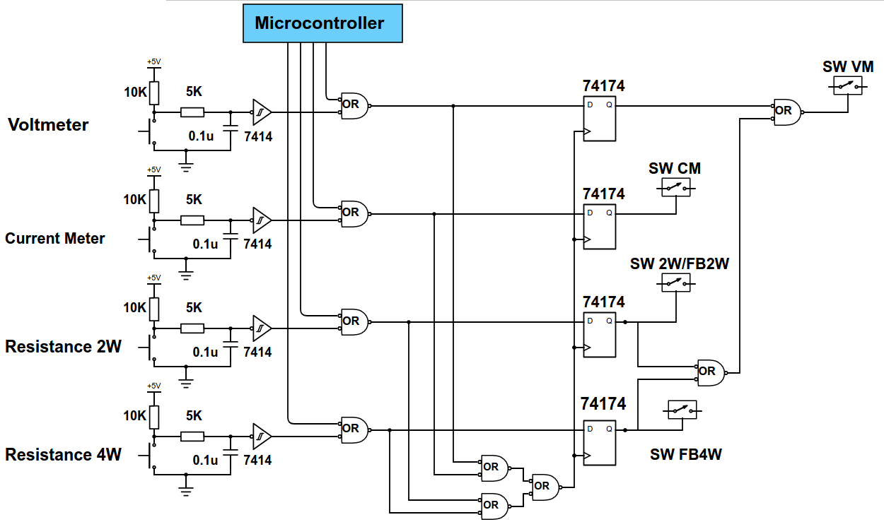
Current Amp digital control - DMM Project - Electronics Circuits

DMM architecture. (a) Partially distributed. (b) Fully distributed
![[Solved] include picture of DMM reading. 1. Wire the circuit below on a](https://i2.wp.com/www.coursehero.com/qa/attachment/18765346/)
[Solved] include picture of DMM reading. 1. Wire the circuit below on a
